This article appeared originally as "Exploded View: Webley Mark VI Revolver" in the May 2003 issue of American Rifleman. To subscribe to the magazine, visit the NRA membership page here and select American Rifleman as your member magazine.
Many firearm experts have called the Webley Mark VI “the finest military revolver ever designed,” and there is much merit in that statement.
The Mark VI, which first appeared in mid-1915, was actually the final installment in a series of top-break service revolvers that were first accepted into British military service in 1887.
While Marks I through V were certainly reliable, robust arms, the Mark VI incorporated all of the virtues of the earlier models and added a few advantages of its own. It was chambered for the Mark IV .455 Webley cartridge, a smokeless-powder round with approximately two-thirds the puissance of a .45 ACP.
The revolver was loaded and cleared by “breaking” it open via a thumb-operated “stirrup latch” located behind the recoil shield. Dropping the frame exposed six chambers where cartridges could be loaded singly or by means of one of the patented “quick-loaders” of the period. The revolver was then closed and when the rounds were expended, it was again opened where a star extractor pulled the spent cases clear of the cylinder.
The gun was double-action, but could be thumb-cocked for deliberate shooting. The stocks were made of checkered vulcanite and were of a squared configuration rather than the rounded bird’s head style of the earlier Marks. The finish was blue. The barrel measured 6” and was fitted with a removable front sight, the rear sight being fashioned out of a notch on the top of the stirrup latch.
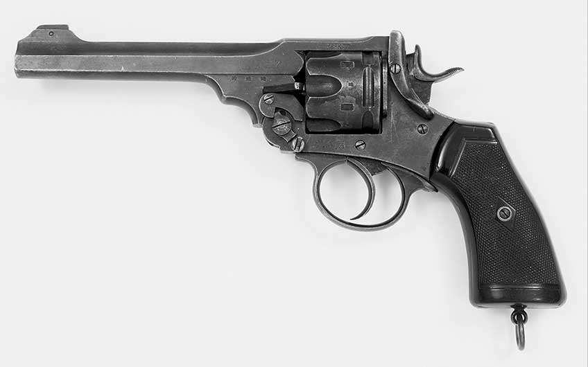
The Mark VI became a staple during World War I, and, while earlier Webleys were still seen in the trenches, it became the pre-eminent sidearm of the British soldier in that conflict. By the end of the war, approximately 280,000 Mark VIs had been manufactured.
Some accessories were devised for the Mark VI, including a detachable shoulder stock and a bayonet that had a wicked-looking blade with a T-shaped cross section. As well, .22 LR training revolvers were devised, as were cutaway versions for firearm instruction. Target models were also offered in the inter-war years.
Mark VIs continued in production by Webley & Scott and (from 1921 to 1926) at the Royal Small Arms Factory, Enfield. Despite being replaced by a smaller, less powerful .380/200 cal. revolver in 1928, the popular .455s were still being cataloged by W&S for civilian use as late as 1939.
Renamed “No. 1, Mark VI,” the Mark VI saw some use during World War II (and beyond) with British and Commonwealth forces where a good number of officers and men preferred it over the issue Enfield No. 2 Mark I.
Many thousands of Webley Mark VIs have been imported into the United States over the years. Some have had the rears of their cylinders ground down 1/16” in order to accept .45 ACP ammunition in half moon clips or .45 Auto Rim cartridges.
While this practice makes the gun more convenient and inexpensive to shoot, it does reduce collector value and interest. It should also be noted that factory-loaded .45 ACP rounds are of too high a pressure to be fired in the Webley. Those using .45 ACP cases should handload to more appropriate levels.
Disassembly
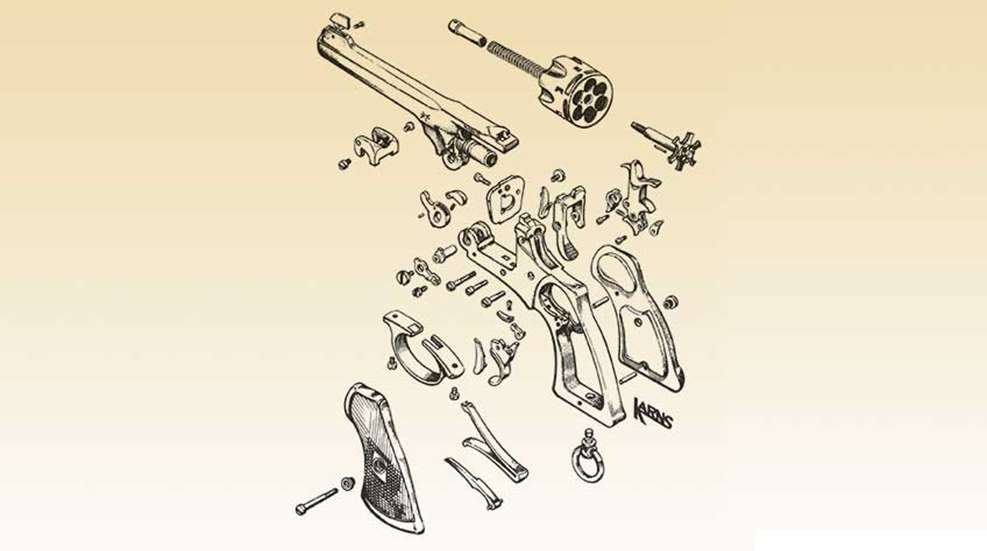
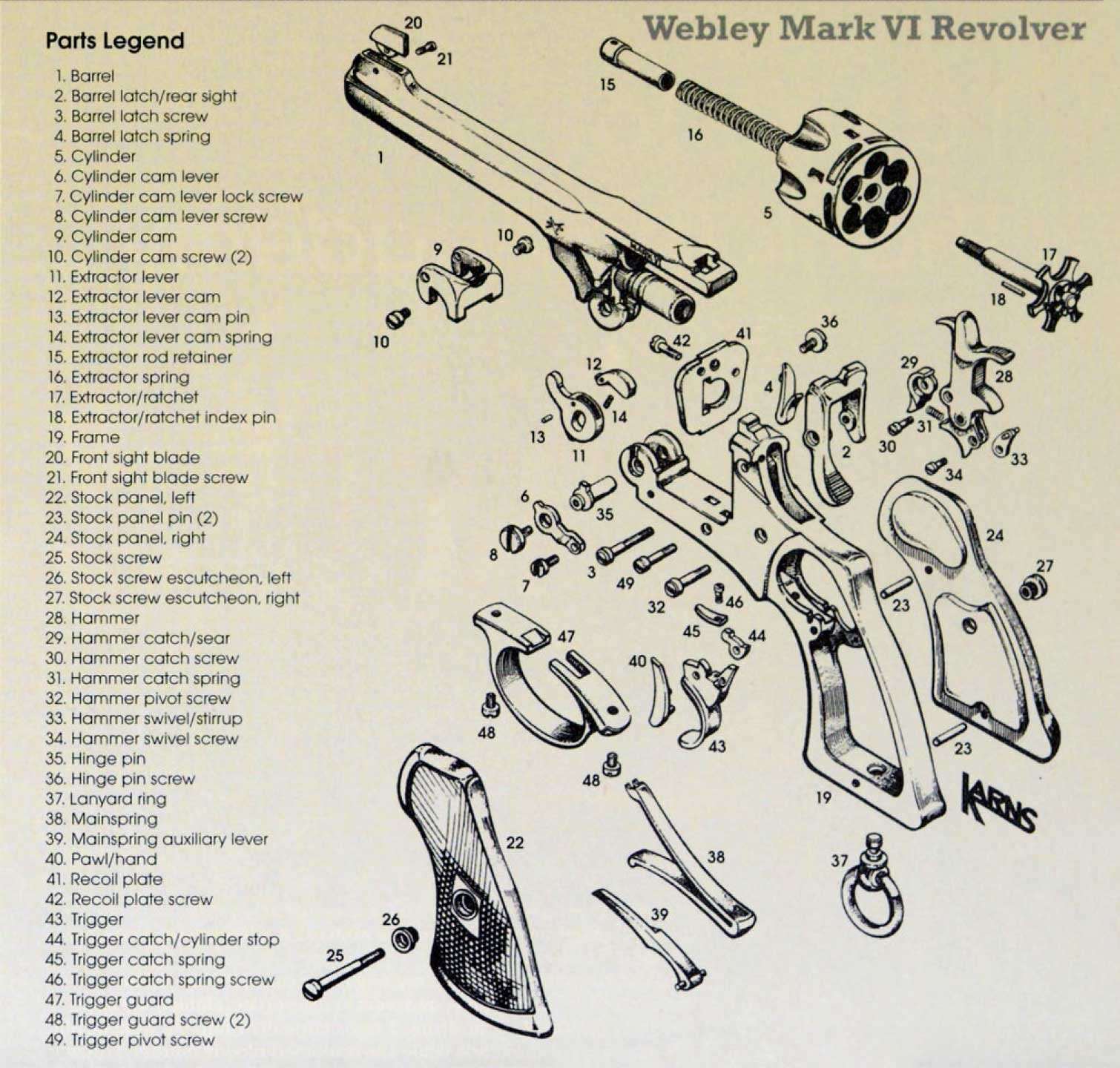
To disassemble the Webley Mark VI, press the stirrup barrel latch (2) forward, open the revolver and ensure it is unloaded.
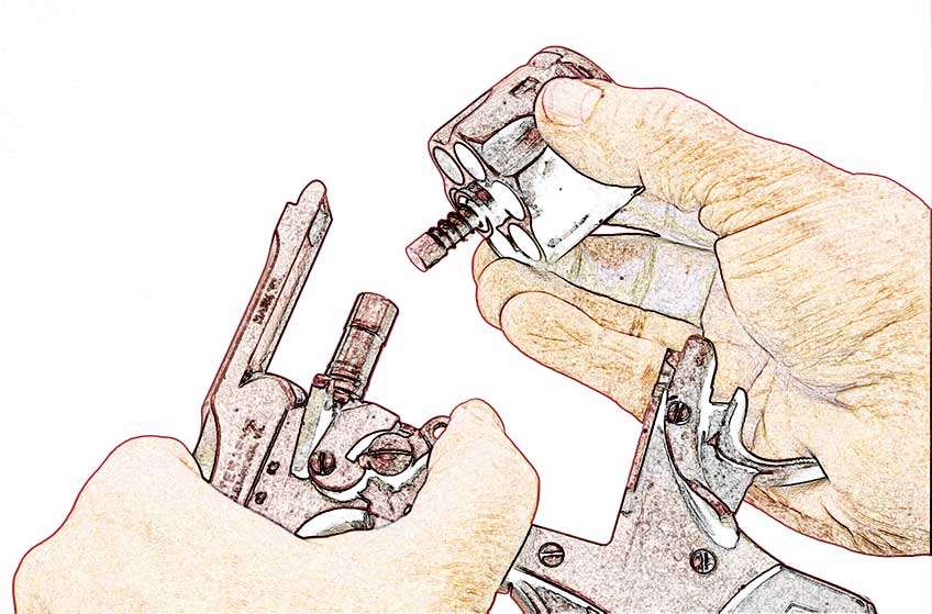
Unscrew the cylinder cam lever lock screw (7) and rotate the cam lever (6) to depress the cylinder cam (9). The cylinder (5) may now be removed from the barrel assembly (1) (Fig. 1).
Remove the cylinder cam lever by unscrewing the cylinder cam lever screw (8). Place a dowel or fired case in a chamber to protect the extractor/ratchet pin (18), insert a punch or nail into the disassembly hole in the extractor rod retainer (15) and turn it counter-clockwise (Fig. 2).
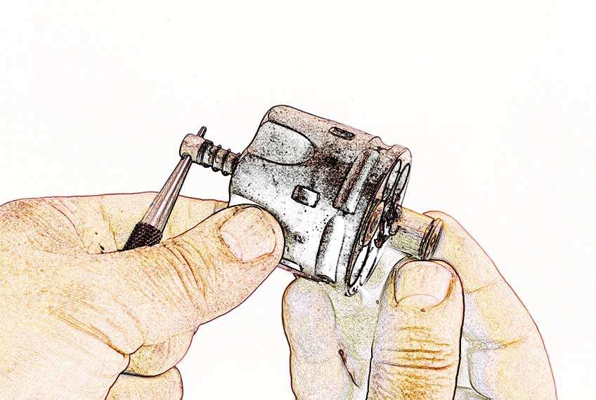
The rod retainer and spring (16) may now be removed from the front cylinder and the extractor/ratchet (17) from the rear.
The barrel is removed from the frame by unscrewing the hinge pin screw (36) and pushing the hinge pin (35) out to the left. Separate the barrel from the frame taking care not to drop the extractor lever cam (12) (Fig. 3).
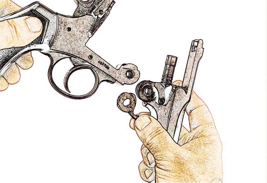
Remove the right and left cylinder cam screws (10) and slide the cylinder cam from the barrel assembly. Remove the front sight blade (20) by turning out the front sight blade screw (21).
To take out the mainspring( 38), unscrew the stock screw (25), remove the right and left stock panels (22, 24) and put the hammer (28) on full cock. Take a piece of wire and slide it through the forward portion of the mainspring. Using a pair of needle-nose pliers, twist the wire until the mainspring is held captive in the compressed state.
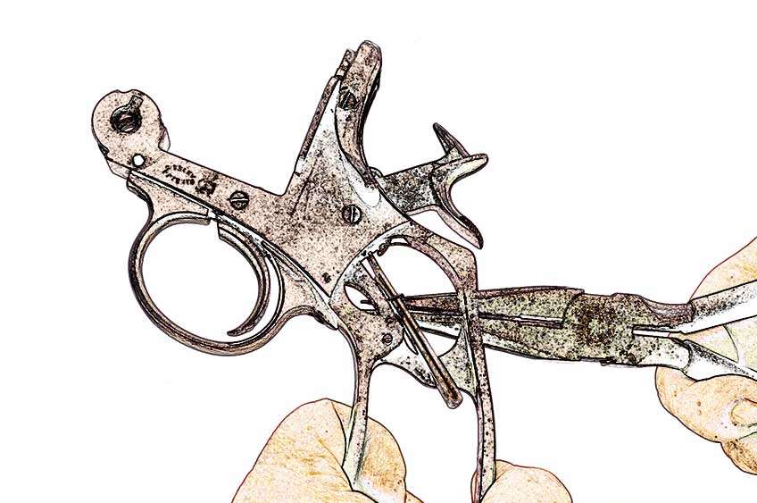
Lower the hammer and disengage the spring’s hooks from the hammer swivel/stirrup (33). The mainspring may now be cleared from the left side of the frame by pulling its integral securing pin from the hole in the right side of the frame (Fig. 4).
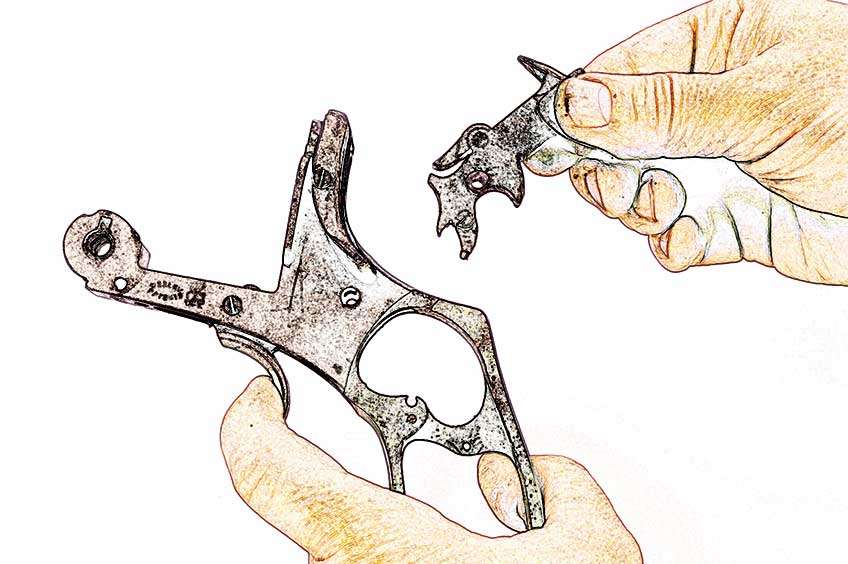
Compress the barrel latch spring (4) using padded pliers and unscrew the barrel latch screw (3) while the spring is compressed. The barrel latch and barrel latch spring may now be taken from the frame by moving the latch down and to the rear and freeing the spring from its retaining hole in the recoil plate (41).
Remove the recoil plate screw (42) and drift the recoil plate sideways out of the frame.
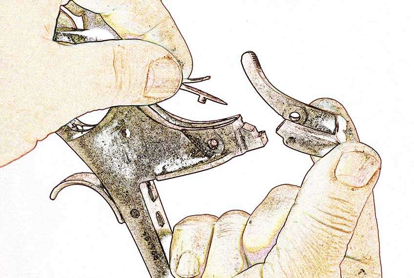
Remove the trigger guard screws (48) to free the trigger guard (47). Unscrew the hammer pivot screw (32) and slide the hammer from the frame. Remove the trigger pivot screw (49) and trigger (43).
Separate the pawl/hand (40) from its recess and take out the trigger catch spring screw (46) to remove the trigger catch (44) and trigger catch spring (45). Reassemble the revolver in the reverse order.


