This article, "Military Rifles: M1 to M14" appeared originally in the in the March 1974 issue of The American Rifleman. To subscribe to the monthly magazine, visit NRA’s membership page.
The adoption of the M1 Garand rifle by the United States Army initiated a series of developments which brought the demise of the manually-operated, bolt-action rifle as a U.S. military arm. Its evolution was to influence the design of U.S. military small arms for years to come.
John C. Garand's basic design and later rifles derived from it served this country well through World War II, the Korean War and during numerous other engagements that blend into recent history.
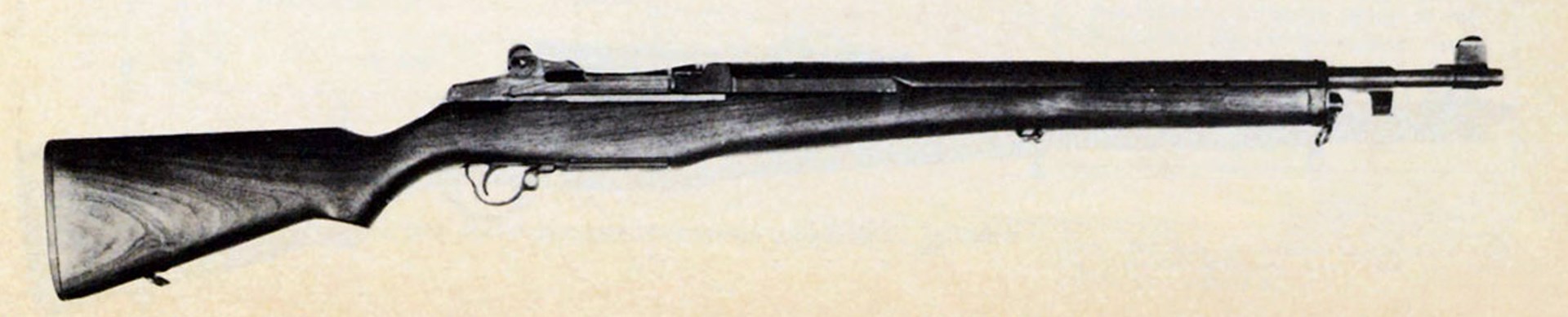
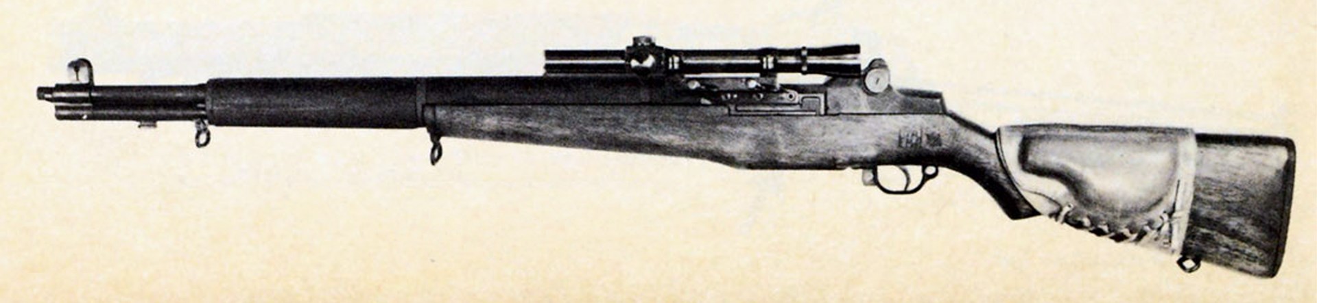
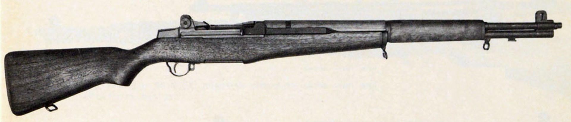 U.S. Rifle Cal. .30 M1, the famed Garand Rifle.
As it was adopted during peace time in 1936, the M1 rifle was not subjected to the acid test of extensive and intensive use by combat troops until after the United States entered World War II. This was in marked contrast to the way in which current M16 and M16A1 rifles were developed during the heat of the recent Southeast Asian conflict.
With the exception of limited use by the U.S. Navy and by Air Force and Navy rifle teams, the M1 rifle has been replaced in actual service by the M14 and M16 rifles. Because of inherent similarities apparent between the M1 and M14 rifles, and the obvious influence of the M1 upon U.S. military arms development, it is unlikely that interest in it will fade for some time to come.
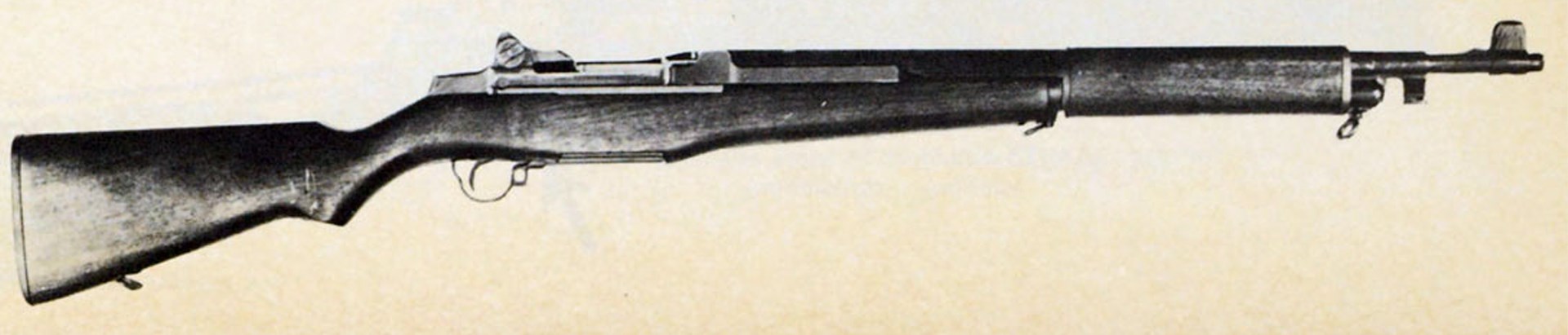 U.S. Rifle Cal. .30 M1E4.
Widespread use of accurized M1's by high power rifle competitors has made them popular with many firearms enthusiasts. Until recent introduction of commercially manufactured rifles having the basic form of the M14 rifle, the M1 was the only arm approved for use in NRA-sanctioned competition (in the service rifle category) and in NBPRP-sponsored competitions which could be owned by civilians.
The evolution and development of the M1 and M14 service rifles are therefore of interest to shooters who now use them, as well as to many who may have carried them under less pleasant circumstances.
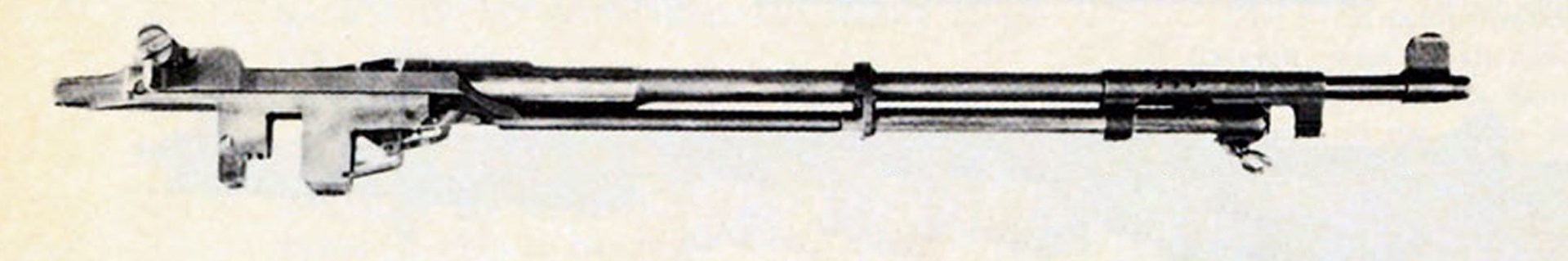 M1E4 Rifle working parts with bolt retracted.
At first glance it might appear as if each of the changes given to the M1 was merely an exercise in engineering serving no particular purpose. More detailed examination indicates exactly the opposite.
The GI who must carry a rifle is usually its severest critic. The Army Ordnance Corps strove to anticipate criticism from combat units in conjunction with exhaustive engineering tests to isolate problems, and introduce needed corrections and modifications as soon as possible. Every change was considered in the light of its battlefield benefit to the soldier.
![]() U.S. Rifle Cal. .30 M1E5 with Stock T6 (stock extended) and M15 Grenade Sight mounting plate (arrow).
U.S. Rifle Cal. .30 M1E5 with Stock T6 (stock extended) and M15 Grenade Sight mounting plate (arrow).
Specific studies were often identified by number and even at this late date, references to experimental rifles as high as M1E12 can be found.
The original alpha-numeric identification of the final experimental version of the Garand rifle was T1E2, and although the rifle was not officially adopted until 1936, this designation was changed on Aug. 3, 1933, to U.S. Semi-automatic Rifle, Caliber .30, M1. While many modifications were made to the rifle and its components, not all were separately identified. A list of the major variants considered during World War 11, together with a brief statement of the purpose of each, follows:
M1—The basic rifle as officially adopted in 1936.
M1E1—The operating rod altered to give a slower cam action.
M1E2—An M1 equipped with a prismatic scope allowing clip feeding and ejection.
M1E3—Modified M1 Rifle bolt having a roller on the right-hand locking lug.
M1E4—The first use of a cut off and expansion type gas system. Piston travel was 4.5".
M1E5—M1 Rifle barrel shortened to 18" and the rifle equipped with a folding stock.
M1E6—Back-up program to M1E2 based on use of a left-side mounted telescope.
M1E7—M1 Rifle mounting a Griffin & Howe telescope.
M1E8—M1 Rifle mounting a telescope on chamber end of the barrel.
M1E9—A derivative of the M1E4 gas system using a long tappet with only 1.5" travel.
Late in World War II, the M1 Rifle became to the military arms field what the Model A Ford and early Ford V-8's became to dirt track racers. In a search for a suitable mechanism capable of selective semi- and full-automatic fire, the M1's basic action was used as the test chassis for a new military rifle, which eventually became the M14. Although many designs were considered, some of those based on the M1 included the T20 series, the T22 series, the T23, T24, and T25.
But let's go back and look more fully at the above-listed alterations to the M1: M1E1—As noted in the preceding list, this designation applied to a rifle with a more gradual cam angle in the operating rod. This innovation was tried out about the same time as certain lubrication tests.
 U.S. Rifle Cal. .30 M1E8. Adjustable cheekpiece shown flush with stock for iron sight use.
During the test of early production M1 Rifles it was observed that when firing unlubricated—a situation likely during periods of heavy or sustained rain when ordinary lubricants could be washed off—the action "froze" after a limited amount of firing. After trying the possible lubricating compositions available at the time, a commercial preparation known as Lubriplate 130-A was adopted. This grease, when applied even sparingly to the bolt cam lug, the firing pin tang, the receiver bridge and the cam cut in the operating rod handle, allowed for longer periods of operation under very wet conditions. This is the grease that was packed in the stock of the rifle with the oiler and cleaning kit. The same material is also used for the M14 Rifle although the M14 has the advantage of a friction reducing roller on the bolt lug. (Later advancements in lubricants have provided a semi-fluid material [Mil-L-46000A] for the 5.56 mm. M16A1 Rifle.)
The tests, however, did not indicate that either the galling effect or the "freezing" of the action was materially improved by the M1E1 modification. This was because the operating rod cam was not the critical point—that was the hammer nose and the corresponding cam in the rear end of the bolt. It appears that this cam was made less steep in U.S.-made rifles after early production; the result was far greater ease of opening and reliability in all the U.S.-made M1 rifles after the quite early ones.
 U.S. Rifle Cal. .30 M1E9.
M1E2—In 1942, when the Springfield M1903A3 Rifle fitted with a telescopic sight was adopted as the U.S. Army "Sniper's" Rifle under the designation M1903A4, Ordnance was asked to fit the M1 with a telescope that would allow clip feeding and functioning in the normal manner. The M1E2 Rifle had a 3X scope offset to the left, but with the eyepiece centered. This arrangement was tested and compared with a straight tube type telescope mounted on the left side of the receiver and using an adjustable cheek pad on the stock. Even though neither construction was approved for service use, the test results pointed up certain characteristics of the M1-Telescope combination useful in later work on the same problem.
M1E3—Kinematic studies and other research directed toward improving the functioning of the M1 Rifle led to the design of a roller lug for the camming lug on the rifle bolt. This required a matching change in the cam angle in the operating rod, and the rifle so modified was designated M1E3. Extensive rain tests conducted at the Springfield Armory and Aberdeen Proving Ground showed that, in comparison with unmodified M1 Rifles, the roller mechanism permitted firing in the rain test up to twice as long as the standard rifle.
This work was completed about the middle of 1944. Because of the advanced production status of the M1 Rifle at that time, the roller bolt was not adopted for production. The design was incorporated, however, in a later rifle, the T20, and then in the T44 series. It is now a part of the standard M14. A similar construction is used on the bolt body of the M60 machine gun to drive the primary feed lever.
M1E4—Despite the fact that many freshman engineering students feel that Kinematics is only a cross they must bear, it is an important subject in the design of gun mechanisms and in the analysis of their functioning and operation. The use of high speed photography and the making and study of time-displacement curves can pinpoint many sources of trouble and suggest mechanism changes to improve operation. Studies such as these, in which dwell times and velocities of operating parts can be detected and measured, led to the development of the gas system used in the M1E4 Rifle.
In this construction, known as the cut-off and expansion system, a small amount of gas is bled from the barrel and allowed to expand in a hollow piston. As this gas expands, the piston moves, cutting off any further supply of gas. Continued expansion, then, forces the operating parts to the rear to cycle the mechanism.
This cut-off-expansion system of the M1E4 Rifle provided a desirable lengthening of the dwell time which dropped the residual pressure at the time of bolt unlock and decreased the velocity of the operating rod. The result of all this markedly reduced the hammering or galling effect on mating parts, with smoother functioning and no increase in total cycle time. Compared with the M1, the M1E4 had slightly more than twice the dwell time, less than one-half the slide velocity at the time of bolt contact, equal velocity at the full rearward position and, as stated above, equal cycle time. In the particular design used, however, the gas was in contact with the piston for the complete length of the recoil cycle, causing excessive heating of the operating rod and operating rod spring. A modified system therefore was developed, and applied in the M1E9 Rifle.
M1E5—This rifle was developed in response to requests, from various World War II Theaters of Operation, for a short, light-weight M1 having a folding stock. Accordingly, the barrel of the rifle was reduced to 18" length from the standard 24" and a metal pantograph-type stock that folded down and forward under the forestock was added to complete the weapon. Testing of the M1E5 disclosed excessive blast and flash from the shortened barrel and also resulted in a request for a partial or full-type pistol grip for the folding metal stock. The rifle having this modified stock was designated T6E3 but was not carried to completion because of higher priority work.
A short M1 Rifle almost saw service during World War II, when, in July, 1945, the Pacific Theater requested such a weapon and provided a model of the type desired. This was essentially the M1E5 assembled with a conventional wooden stock. As plans were being finalized for the limited procurement of 15,000 of these weapons, VJ-Day occurred and the requirement was cancelled.
M1E6—This designation covered a design study for an M1 Rifle equipped with a left side mounted telescope and a ramp sight similar to that on the M1903A3 rifle. The objective here was to permit use of the iron sights while the telescope remained installed on the rifle. The study resulted in the decision that this would be undesirable because of extensive modifications that would be required on production M1 receivers.
M1E7, M1E8—Although the M1E2 and M1E6 rifles never saw service, a requirement remained for the development of a "Sniper's" Rifle based on the M1 mechanism. This is not to suggest that there were deficiencies in the M1903A4 rifle, which was the famous Springfield fitted with a scope. Rather, it was a natural and necessary step toward simplifying the logistics of having two different rifle designs in the field with different spare parts. The ammunition, of course, was no problem, since both rifles were chambered for the .30- '06 cartridge.
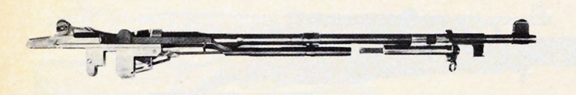 M1E9 Rifle working parts, with bolt half retracted and gas piston fully back.
The basic difference between the -E7 and -E8 Rifles is in the method of mounting the telescope. At the time the development was started, two designs were considered. The M1E7, also referred to as the Griflin & Howe design, had a dove-tailed, cam-operated pressure plate attached to the left side of the receiver; the M1E8, in order to preclude any machine work on finished, hardened receivers, used a special mounting block attached to the chamber end of the barrel. Although this required a shorter rear hand guard than in the standard military rifle, wood is far easier to work than 8620 steel hardened to Rockwell C55 to C59.
Since the basic design of the Garand Rifle required the top loading and ejection of the en bloc clip, the Sniper's Rifle had to take this into account. Consequently both the mounting designs noted provided for offsetting the scope to the left. As a result of this, we have the story of a development within a development.
Initially, the -E7 and -E8 Rifles were fitted with a check pad that could be fastened to the wooden stock by lacing. This pad, identified as the T2, was of leather and provided three thicknesses of cheek support, fastened to the leather base by snap fasteners. Simplification of the T2 design eliminated the snap fasteners and permitted the addition of three different thicknesses of felt padding. This type was designated T3 and was adjustable by removal or insertion of the felt increments. Still later the T3 was redesigned to allow retention of the felt increments, and fastening the check pad on the stock by a single lacing instead of two. Result? The T4 Cheek Pad.
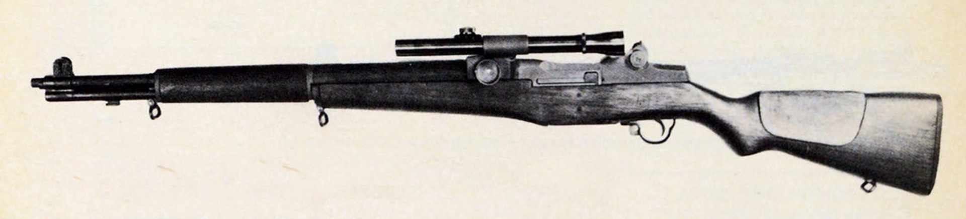
 U.S. Rifle Cal. .30 M1C right-side view shown with riflescope and cheekpad.
But though sniper rifles were eventually supplied with the T4 Cheek Pad, the T4 is not the end of this vignette. A duplication of the T4 was produced from polyvinyl chloride as a leather substitute and designated T5. The original models of the M1E8 Rifle had a cord-covered, adjustable metal Cheek Pad T6, assembled to the stock. This design was modified once to provide more face support and redesignated T6E1, but informal testing late in 1944 resulted in the recommendation that no further consideration be given that construction.
The Leather Cheek Pad, T4, was formally adopted for Sniper's Rifles in Oct., 1944.
The M1E7 Rifle was standardized as the M1C in June, 1944. To make certain that production sources could meet requirements, the M1E8 Rifle was adopted in addition during Sept., 1944, as the M1D.
Telescopes used with the M1C and M1D Rifles were 2.5X. There were two forms, one equipped with a crosswire reticle and the other a tapered post. Both scopes had rubber eyepieces and rain-sun shields. The eye relief on both sights was about 5", and thus quite long.
M1E9—The significant feature of the M1E9 Rifle can be inferred from the history of the M1E4. To eliminate the heating encountered in the -E4 design, a long piston with a shorter stroke was used. In this design, which again was a cut-off expansion-type gas system, the piston moved back about 1.5" instead of the 4.5" of the M1E4. The energy to cycle the mechanism could be transferred through the operating rod in the time required to complete this motion. When the piston came to a stop, the operating rod and bolt continued to the rear through inertia. Again, the total cycle time was equivalent to that of the standard rifle. The far-advanced production status of the M1 Rifle at that date, however, did not warrant major redesign of the M1 Rifle to incorporate the new gas system.
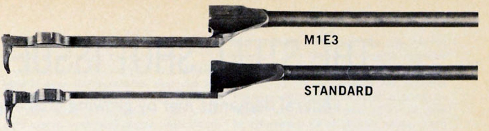 M1 and M1E3 operating rods comparison.
The World War II History of Small Arms Development by the Ordnance Corps records that ". . . the design is contemplated for use in a post war development project of a new rifle." Any readers who have disassembled the M14 7.62mm. Rifle have seen the gas system first used on the M1E9.
Another design modification for the basic M1 Rifle was identified as the M1E10. This was an attempt to apply the Ljungman type of gas system in place of the standard impingement system. Although gas would be tapped from the barrel at about the same point (and at the same pressure), the Ljungman system pipes the gas to the point of application on the bolt assembly. Thus the use of the long operating rod with its manufacturing and maintenance problems might be avoided.
While no examples of this modification of the M1 are known to have been built, the gas system has found application in the Armalite series of rifles, the AR-10 and AR-15, and the M16/ M16A1 rifles. The reader should not infer, however, that just because the Ljungman gas system has the advantage cited it is necessarily good. Many factors in addition to ease of production must be considered for military weapons. A significant drawback to this type of gas system is the very basic fact that distance can be equated to time. And "time" for a hot gas means cooling. When hot propellant gases cool, trouble happens. Without a proper choice of propellant or without due regard for propellant chemistry, gas tubes clog, bolt mechanisms get dirty, and rifles malfunction. When this combination of events occurs during the height of a war, considerable effort and technical talent must be brought to bear on the problem. The current excellent performance of the M16 rifle system is a testimonial to the fact that this was done.
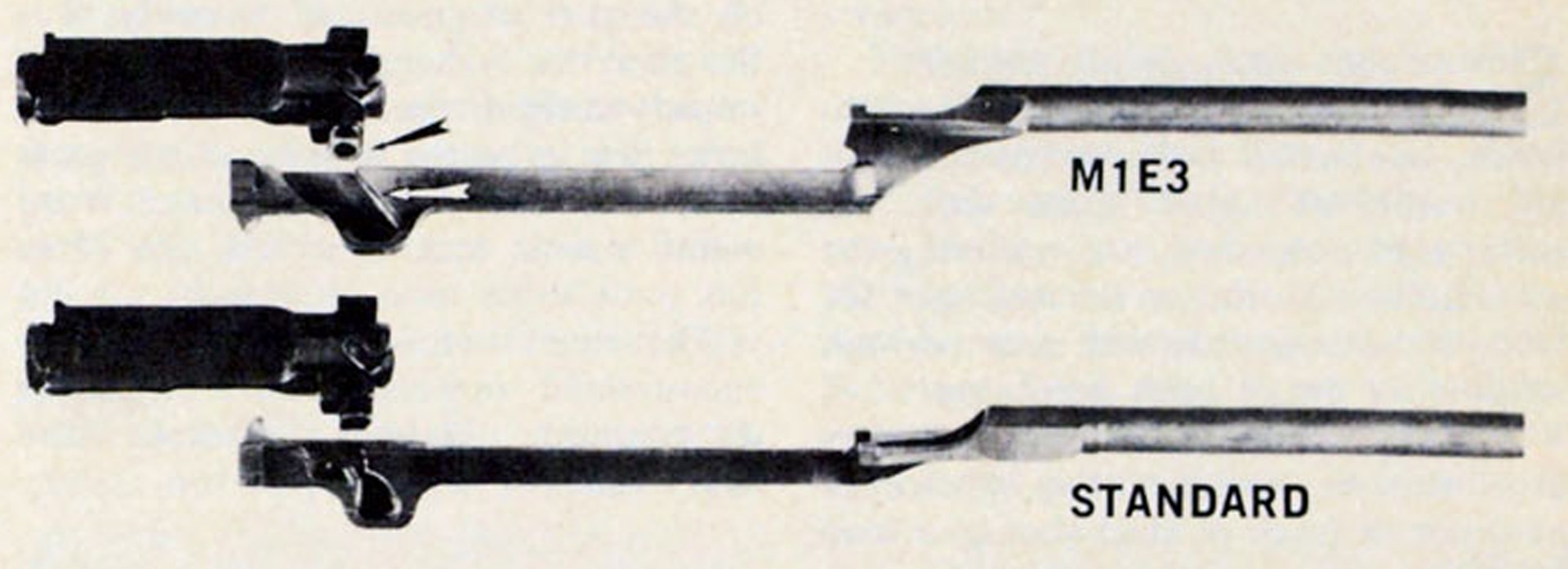 M1 and M1E3 operating rods and bolts compared. While the M1E3 type was developed too late for use in the M1 rifle, it eventually became part of the M14 rifle and M60 machine gun.
Other variations of the M1 Rifle may not have been generally noted. Take, for example, the M1 E5, described earlier as the folding stock development of the M1, which almost saw service during World War II. The 15,000 which were planned for production for Pacific Theater use just prior to VJ-Day were M1E5's, but they would have been officially identified as Rifle, Cal. .30, T26.
The M1 Hangs On
Although the M1 Rifle began to be phased out of the U.S. Army as early as 1959 with the equipping of the 101st Airborne Division (and soon thereafter, the Berlin Garrison) with the M14, modifications to the basic M1 were still attracting attention on various drawing boards and in the chambers of those concerned with government economy. These included even changes for the use of different ammunitions. The similarity between the M1 and the M14 in terms of mechanical modifications developed and tested for the older weapon that were applied to the newer has already been noted in this article. Now, how does the ammunition come into the picture?
Notice on the diagram that the overall length of the 7.62 mm NATO cartridge is 1/2" less than the 3.30" overall of the venerable .30-'06. Other dimensions are comparable. Cartridge head diameters, for example, are the same. Thus, if a NATO cartridge profile were placed atop a chamber drawing for the M1 Rifle, it is apparent that to use the 7.62 mm NATO cartridge in an M1 Rifle a spacer or bushing would be required in the front of the .30-'06 chamber. Such a sleeve or bushing was designed and methods for installing and using it were developed by the Naval Ammunition Depot at Crane, Ind., in 1963. With bushings supplied by the Navy, the Army made up some models identified as M1E12. These were tested by the Springfield Armory and Aberdeen Proving Ground.
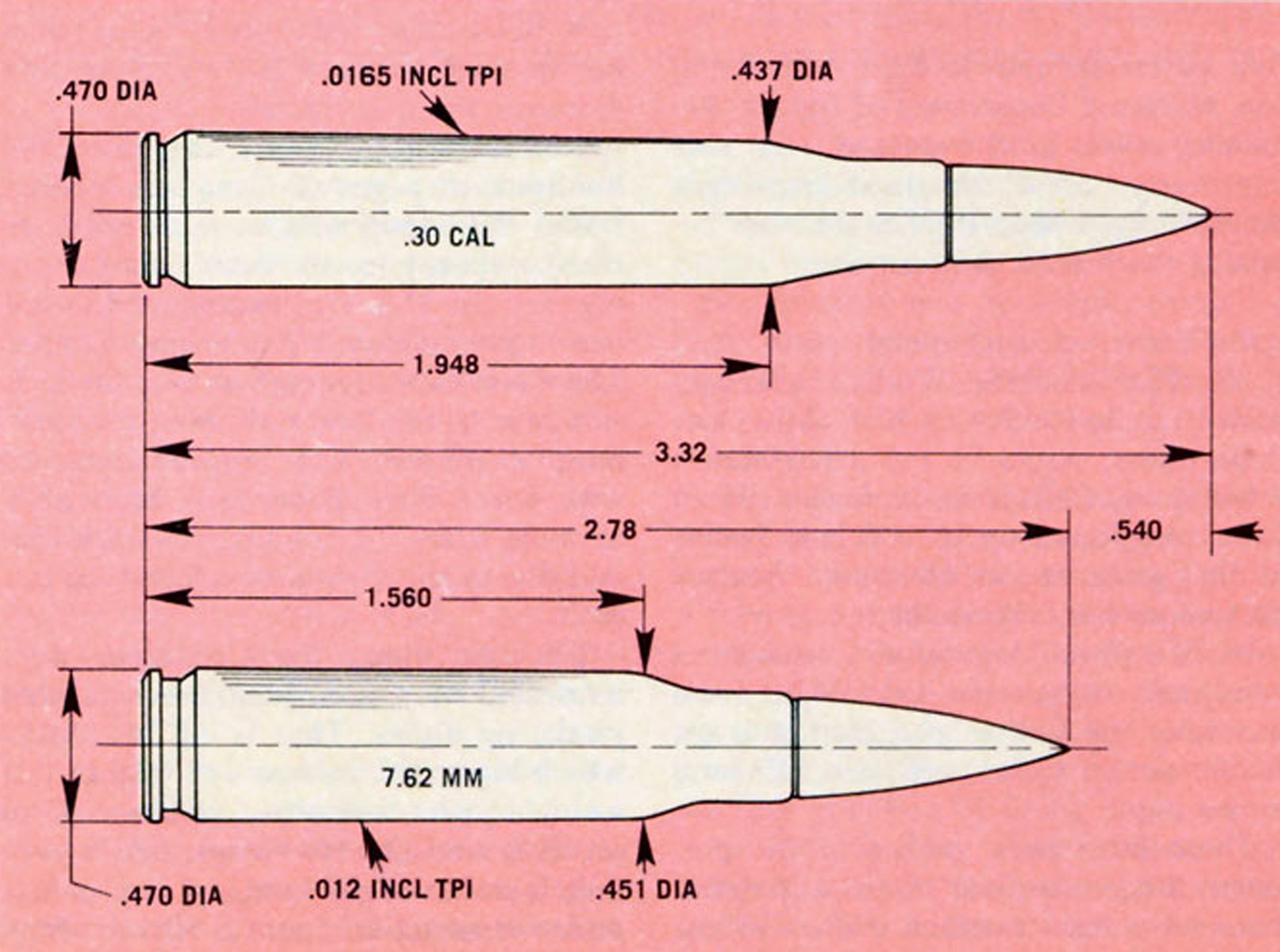 Cal. .30 and 7.62 mm NATO cartridge dimensions compared.
The modification was not adopted, however, because the safety phase of the test showed that the bushings as then made could occasionally be extracted with a spent case. Should this occur, the next round might leave the face of the bolt on being chambered and remain in the chamber, unextracted and unfired. A succeeding round, if the shooter followed the usual procedure and cycled the action rapidly, could conceivably be driven into the primer of the unfired round already in the chamber. The resulting out-of-battery explosion represented too great a safety hazard to be considered by the Army for a Service weapon*.
Modifications like the M1E12 are dictated by economic as well as technical factors. The tremendous investment in ammunition (in depot storage as well as in the supply pipeline and in the hands of operational units) justifies consideration of such alternatives as this.
Another alternative for the M1 in 7.62 mm NATO caliber was identified as the T36. This was an M1 with a standard M1 barrel blank made with the 7.62 mm NATO chamber in it. This construction is much to be preferred from a safety point of view, but performance was not as good as desired. Since the policy decision was made for a thorough modernization of the Army's infantry weapons, this design, too, was dropped. (As a matter of interest, some match-conditioned M1 Rifles have been rebarreled in 7.62 mm. NATO caliber for match use and found to shoot with exceptional accuracy.)
On the other side of the economic coin, if a nation already had, relatively, a large investment in weapons, but was anxious to support the NATO concept of the modernized cartridge, a rifle modification might be a feasible solution for updating the weapon inventory. Italy, in the late 1950's, was in this position. The Italian Government had a supply of M l Rifles being built with machinery furnished under the Marshall Plan. Both the rifles and the machinery were reasonably new and capable of substantially greater service than given to that time. While this may be speculative rationale, the Italian firm of Pietro Beretta & Sons has, in fact, built in quantity the BM-59. Based on the M1 chassis, the BM-59 includes the M14 Rifle features of a hinged buttplate, 20-round magazine, modified gas system, and bipod, as well as selective semi- and full-automatic fire. The BM-59 is a standard rifle for the Italian Army.
*While this was the Army experience so far as the Army carried it, the matter was pursued by the Navy as given in Col. E. B. (Jim) Crossman's article, M1 Rifle Conversions to 7.62 mm NATO, The American Rifleman, Dec., 1965, pp. 38-42, and the Navy adopted it.
—T. E. Cosgrove