In all the history of U.S. military small arms, one of the most celebrated and renowned rifles is none other than the M1 Garand. The brainchild of Canadian-American inventor John C. Garand, the M1 design took more than two decades to develop and was a marvel of the time, when adopted in 1936, as the first mass-produced, standard-issue, semi-automatic infantry rifle. It was soon put to the test in World War II, where it emerged as a symbol of American riflemen from the greatest generation. Yet despite the long, hard work of Garand and Springfield Armory engineers that was put into developing the design, it continued to undergo small adjustments and alterations from its adoption to well after the war ended.
Some of these changes were made for ease of production, while other were made to address issues. The better-known examples of these alterations include the change from "gas trap" to "gas port", the "seventh-round stoppage" fix and the addition of relief cuts to the operating rods in the post-war period. Another involved one of the M1's most recognizable features: its rear sight assembly. Here, we will examine the history of the M1's rear sight development from the pre- to post-World War II era.
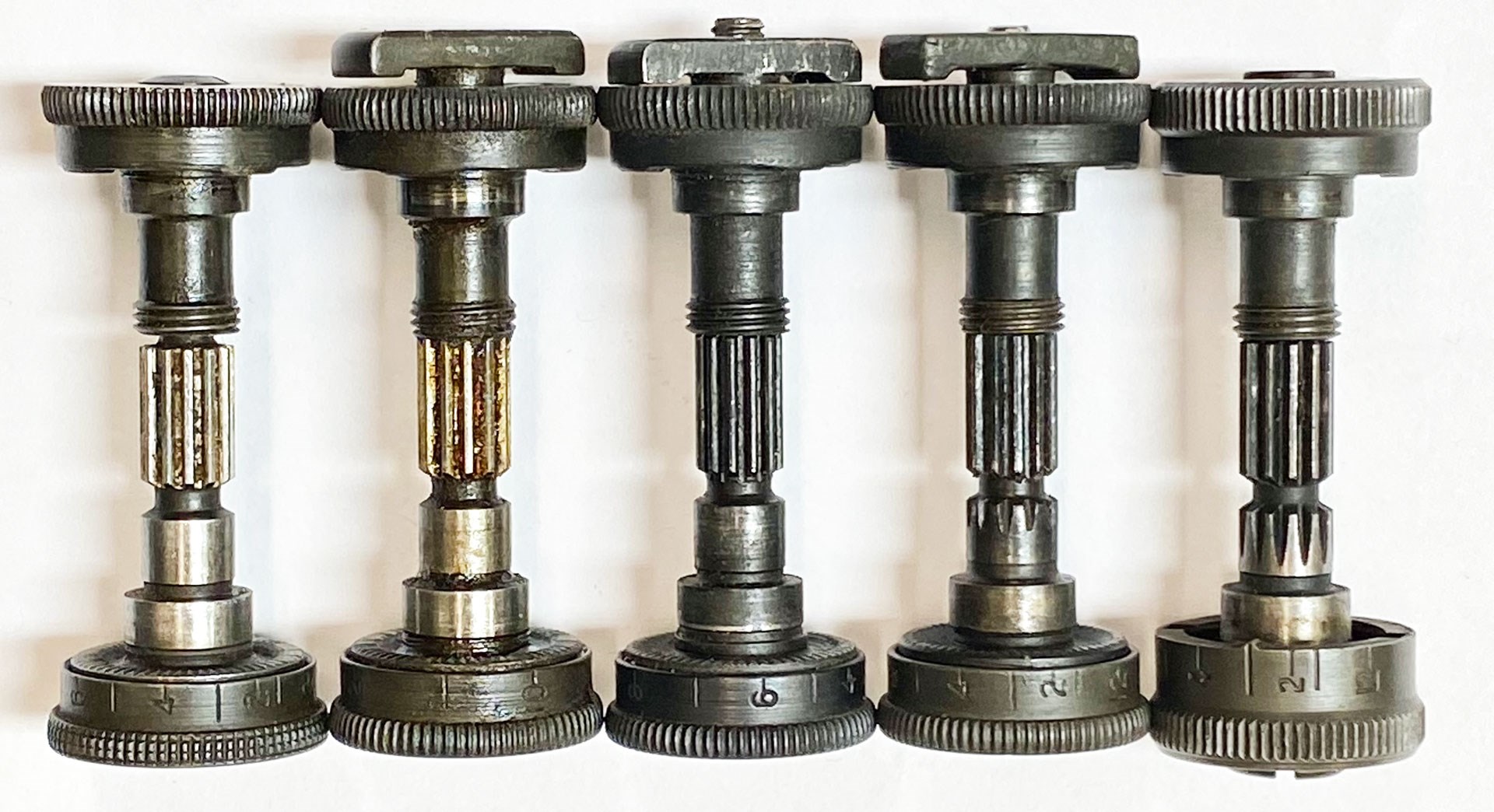 The various versions of the M1 Garand rear sight knobs and pinions used throughout Springfield Armory production. They include, from left to right, the flush nut with short pinion, type one locking bar with short pinion, type two locking bar with long pinion, type three locking bar with long pinion and a T105E1 assembly.
However, it is important to note that most of the alterations to the M1 rear sight assembly were developed and implemented by Springfield Armory during World War II, and were settled before International Harvester Co. and Harrington & Richardson Arms Co. began making rifles in the post-war period. While Winchester Repeating Arms also produced rifles during World War II, from late 1940 to mid-1945, the firm did not keep up with the design changes made by Springfield Armory and even used some unique aesthetics on its own rear sight assemblies. For those reasons, we'll focus solely on the development of the rear sight assembly as made by Springfield Armory.
A Comparison With Prior Service Rifle Sights
When the M1 was officially adopted in 1936, several of its features marked a departure from what the American infantryman had been accustomed to in prior service rifles. This wasn't only limited to its en-bloc clip feeding and semi-automatic function, but included the arrangement of the rear sight assembly as well. On the prior 20th century U.S. service rifles, namely the bolt-action M1903 and M1917, the rear sight designs were of the folding-ladder variety, with two sights.
These included a "battle" sight, which could be used with the ladder folded forward, and an adjustable sight on the ladder itself. The battle sight on these are fixed in place and do not allow for range adjustment. They are also generally set for a relatively far distance, resulting in high shots within 200 yards. In order to adjust the range setting on the M1903 and M1917, the adjustable sight piece must be physically moved up or down along the track of the graduated ladder to the desired range, and the ladder itself must be raised into the upright position.
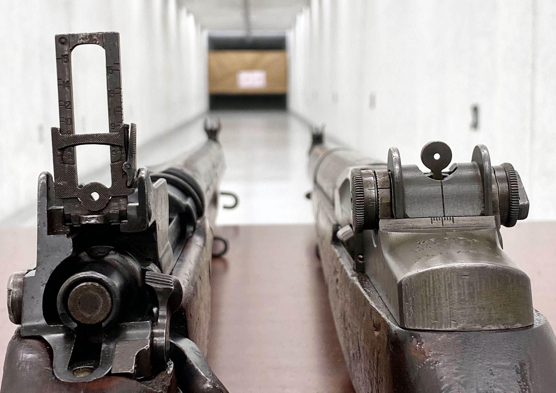 The ladder rear sight of a 1918-produced Remington M1917 on the left, compared with the rear sight of a 1944-produced Springfield Armory M1 Garand, with a type two locking bar and long pinion assembly, on the right.
While the M1903's rear sight does have a windage-adjustment knob, the M1917 has no such adjustment feature, aside from the dovetailed front-sight post which would require the work of an armorer to adjust. The M1903's windage can also be finicky to adjust, as it has no tangible "clicks," and requires a careful hand to make small corrections. While the ladders of both designs can fold to the front or rear in order to reducing snagging or damage, they are still exposed in the raised position and are rather large, obscuring a bit of peripheral view. On the M1, the rear sight is radically different.
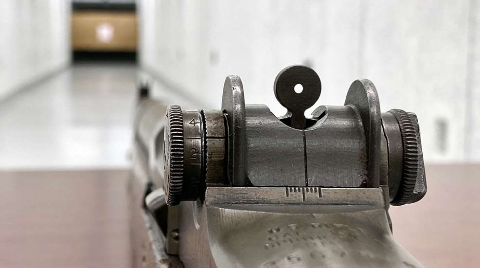
Rather than using a folding ladder with dual sights like the prior rifles, the M1's rear sight is comprised of a single adjustable aperture housed in a low-profile base assembly, with two knobs on either side of the receiver to adjust windage and elevation. To set elevation, the M1's rear sight simply requires the elevation knob to be rotated, which in turn moves the aperture. The same is true of the windage knob, which moves the sight base. Both the windage and elevation knobs also have tangible clicks, with each signifying 1 m.o.a., or a 1" shift at 100 yards, allowing for more precise adjustment.
While more complex internally than the ladder sight designs of the prior rifles, the M1's rear sight assembly is more protected, robust and offers a clearer sight picture. While the rifle the M1 officially replaced, the M1903, uses a notched rear sight, the use of an aperture sight on the M1 was nothing too new, as the M1917 also features it. Though, at the time of adoption, gripes were made about the use of an aperture instead of a notched rear sight, due to the familiarity that had been built up with the M1903.
Basic Layout and Function
The M1's rear sight assembly is comprised of several separate components. These interconnect with the receiver, which has a specific mounting point and "ears" into which the separate components mount together through via threads and spring pressure. The aperture piece slides into a rear sight base, which is secured by a cover that doubles as a spring. This cover snaps into reliefs in the receiver. Both adjustment-knob assemblies intersect through openings on the sides of the base and receiver, and index with serrated cuts in the receiver ears, which produce the tangible adjustment clicks. The left knob assembly controls elevation adjustment and features screw teeth on its pinion, which interact with teeth at the bottom of the aperture piece to move it up and down.
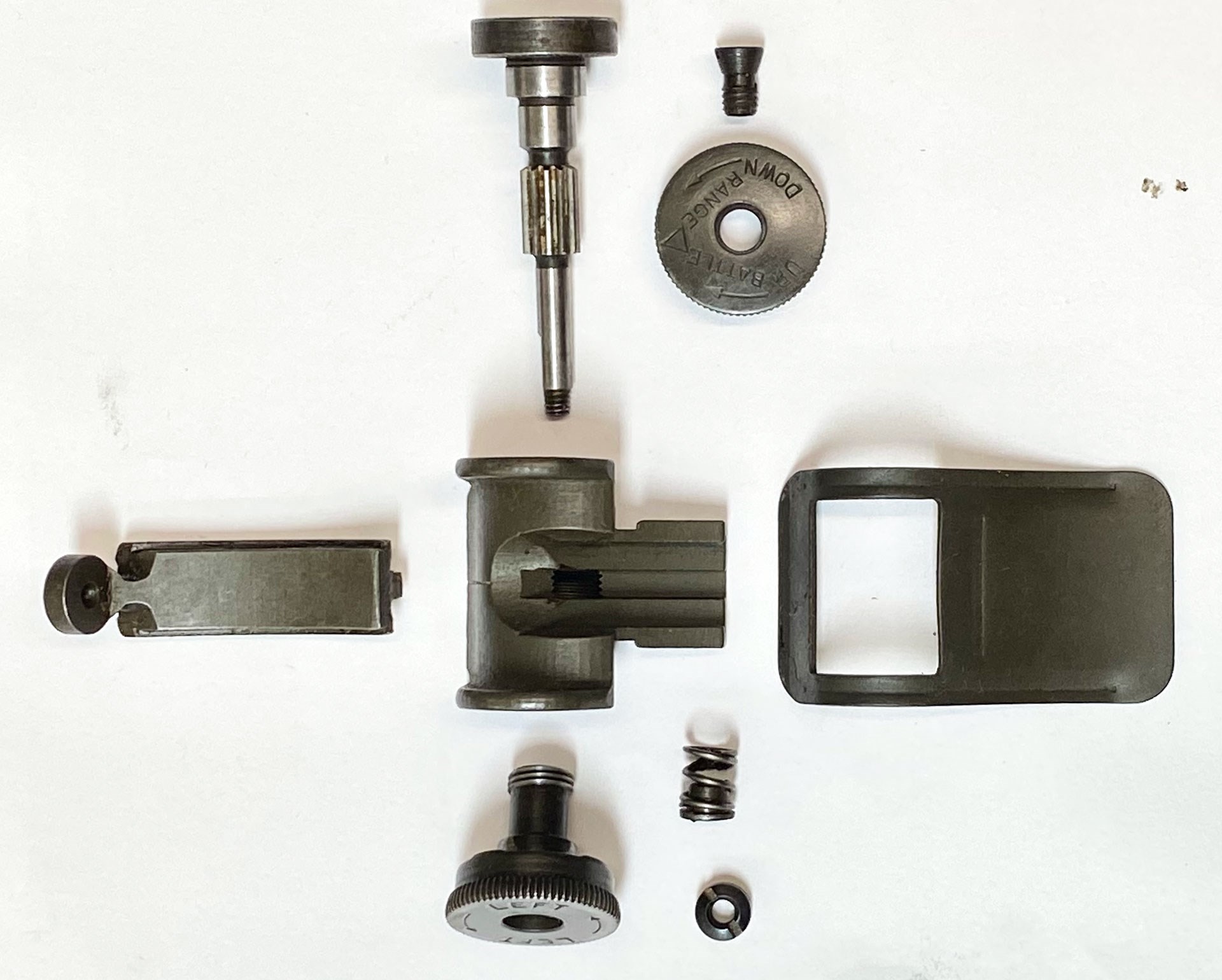 A fully dissembled M1 rear sight assembly laid out. This layout represents a flush nut rear sight assembly that would be found on a mid-1942 produced M1 from Springfield Armory, and is roughly the same as the assemblies that came on earlier rifles aside from the stamped cover, knurled windage knob, lack of part numbers and other early aesthetics.
The right knob assembly controls windage adjustment and screws into the sight base. As the windage knob turns, it pulls the sight base and aperture as a whole to the left or right. Both the elevation and windage adjustment-knob assemblies attach to each other, with a threaded portion at the end of the elevation-knob assembly's pinion being secured by a nut housed on the windage-knob side. A spring is used to provide tension between the two knob assemblies. Even as changes were made to the design, these basic functions of the rear sight assembly remained the same throughout the M1's service history.
The Flush Nut
When the M1 was first introduced the components of the rear sight assembly, much like many other features of the rifles at the time, were made of milled steel. They were well machined and even featured part numbers stamped into some, including the sight base, cover, aperture, pinion, and under the knobs. The initial version of the rear sight assembly consisted of 10 separate components. Most of these components make up the elevation and windage knob assemblies, with the elevation knob consisting of three separate parts while the windage knob has four.
For the elevation side, the early components included a pinion, knob and a screw. The pinion itself on the pre-war and wartime types of M1 sights have serrations machined into the bottom face, which interact with the serrations on the receiver. This initial version of the pinion was flush with the side of the windage knob when installed, and features a short section at the end with 6-40NF threads. The elevation knob mounts onto the pinion with the screw. The knob features a machined edge to provide grasp for making adjustments, with the initial versions being checkered. On the inside face of the knob dial are graduations from 100 to 1,200 yards.
 The three components that comprised the elevation knob and pinion design used on early M1 rear sight assemblies, the pinion, knob and screw.
The outer face of the knobs feature the words "BATTLE RANGE" inscribed, angled towards a triangle. This indicates the location of the 300 yard mark on the graduated portion of the knob, which is the range setting for a battle sight. There are also directional arrows with the words "UP" and "DOWN", indicating which way to rotate the knob for increased or decreased elevation.
Because the knob can separate from the pinion, once a desired zero has been set at one of the specific ranges marked on the graduated dial, the knob can be adjusted to that range and aligned with a notch machined into in the side of the receiver. The graduations are calibrated with the standard ballistic pattern of the military specification .30-'06 Sprg. cartridges. Once the knob is properly set, any adjustment to another range will compensate for bullet drop.
For the windage side, the early components consist of a knob, spring, detent and a slotted nut. The knob makes up most of the assembly on this side, with the spring, detent and nut fitting within a recess in the center of the knob. The windage knobs of early production M1s also featured a checkered edge like the elevation knob. Inscribed on the side of the knobs are the words "LEFT" with directional arrows, indicating adjustment directions. A vertical line on the back of the sight base lines up with windage adjustment not marks on the receiver, with each notch representing 4 m.o.a. adjustments.
 The four components that comprised the first iteration of M1 rear sight windage knob assembly, the knob, spring, detent and flush nut.
The slotted nut functions as a retainer for the spring, and keeps the knob assemblies connected. These early nuts are flush with the sides of the windage knob, earning them the nickname of "flush nut" in the collector community. They interface with the underlying detent for retention, provided by the force of the spring. Adjustments can be made to the tension of the sight system by tightening or loosening this nut, though the interrupted slot on the face of the nut makes adjustments difficult, if not impossible, without the proper tool.
Pre-War Changes
The M1 rear sight assembly stayed roughly in this from from the beginning of production to the early years of World War II, though several small changes were made along the way. These consisted of part simplifications as Springfield Armory worked to find way to make components of the rifles cheaper and easier to machine. One of the most notable changes include the several early variations of the sight cover. The cover went through a few rapid changes from being made of milled steel to stamped steel with reinforcing indentions added by 1940. By the end of that year, the part numbers on all the sight components were also deleted.
 A later stamped sight cover with reinforcement indentions on the left compared with an earlier sight cover on the right.
Springfield Armory also simplified the designs of the knobs slightly, with the checkered pattern of the knobs being simplified. In 1941, the windage knob was changed from a checkered pattern to knurling, which took less time to machine. This is the form that the windage knob would remain throughout World War II production. The elevation cap was also eventually changed to a knurled pattern by the fall of 1942 and would also retain this form throughout wartime production.
The Locking Bars
Once the United States entered World War II after the attack on Pearl Harbor on Dec. 7, 1941, the M1 was thrust into its first combat use. The rifles did well, and began to earn the praise and respect by the men who carried them. However, with the environments of the various battlefields and the wear and tear associated with combat use, issues began to creep up. One of these issues involved the rear sight assembly, namely the flush nut.
The nuts were not captive to the short pinions, and could come loose with use. This would result in the loss of proper tension to retain the knobs on there holds, and could result in wandering or lost zeros, and thus inaccurate shots. Worse still, if the nut were to completely fall off, all tension for the rear sight assembly would be lost and the assembly could fall apart, resulting in a completely useless rear sight. The issue needed to be resolved quickly, and a simplistic place-holder solution was developed.
 An early-war short pinion assembly, with a flush nut and type one locking bar compared.
A crossbar with a threaded hole in the center was designed to take the place of the flush nut, which sits on top of the windage knob when threaded onto the pinion. This bar can be manually loosened or tightened by hand, without the need of a special tool. When loosened, elevation and windage adjustments can be made. Yet when the bar is fully tightened, it compresses the spring and butts up agains the windage knob, locking both knobs firmly in place. This function earned these crossbars the nickname of 'locking bars,' and they were implemented into production starting in early 1942.
This first iteration of the locking bar is often referred to as the "type one" locking bar. Its edges are rounded with the edge of the windage knob, and the tops were slightly rounded as well. Since the type one bars mounted onto the short pinions, they can be readily recognized from other versions when installed due to the small diameter hole in the top, which extends past the length of the short pinion.
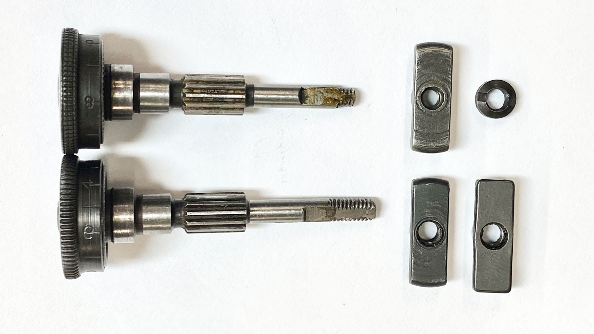 A short pinion with 6-40NF thread used at the beginning of World War II production with a flush nut and type one locking bar on top, compared with the long pinion with 8-36NF threads with type two and type three locking bars used for the rest of wartime production on the bottom. Note the earlier checkered pattern on the top knob versus the later knurled version below.
While the type one locking bar was an improvement over the flush nut and easier to work with, it still has one of the original issues of the flush nut, retention. With the bar simply threaded on, it was possible for the bar to be completely screwed off and result in the same debilitating issue as losing a flush nut. Thus another iteration of the locking bar was developed.
Externally, this new locking bar had the same appearance as the type one, but with a different pinion. To prevent the issue of the locking bar unscrewing and being lost, the pinion was redesigned with a longer threaded section and the thread pitch changed to 8-36NF. The tip of the longer pinion is flush with the end of the locking bar when fully tightened, and features a small hole bored into the center of its tip. This allows the pinion to be staked, and thus prevent the locking bar from fully unscrewing.
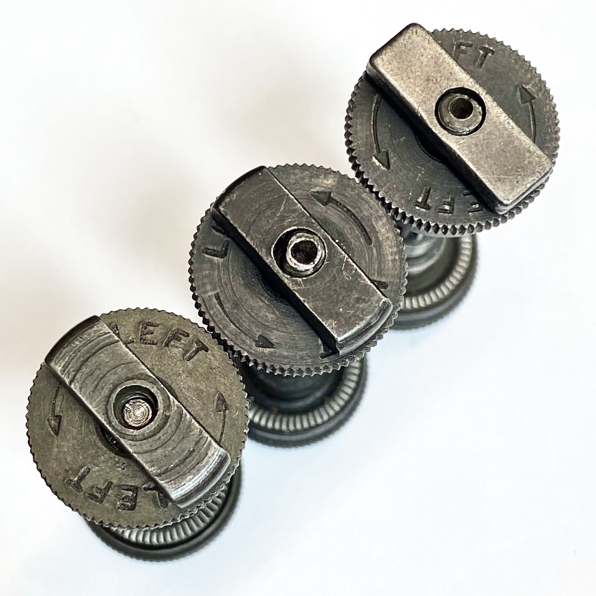 A comparison of the three different types of locking bars used by Springfield Armory during World War II production. From left to right, the type one, type two and type three. Note the the staking holes in the long pinions of the type two and three compared with the short pinion and type one.
This iteration of locking bar also features an enlarged hole on the face, which allows the clearance for the longer pinion to be staked. These locking bars are known as the "type two" variation, and entered production at Springfield Armory starting in late 1942 to early 1943 when the long pinion came into use. Type two locking bars are distinct in that they have the rounded edges like the type one, but the long pinion can be easily seen in the top hole.
The type two locking bar remained in production until the spring of 1944, when it was phased out of production for a more simplified bar with squared off edges known as the "type three" locking bar. While the shape of the type three is different from the type two, it functions in the same way and mounts to the same style of long pinion. Its development was purely to make the bars easier to manufacture, and it was used in rifle production up to the end of World War II.
The T105 And Post-War Era
While the introduction of the long pinion and locking bars worked well in addressing the issues of the flush nut and short pinion, it was still less than ideal. It required the bar to be loosened to make adjustments and then retightened before firing, making adjustments less time expedient. The locking bars were considered to be a place-holder fix, rather than a proper solution. Development of a redesigned pinion and knobs assembly began during World War II, and was finalized in 1944 as the T105E1.
The T105E1 knobs and pinion assembly are notability different from the prior knobs and pinions that were used in pre-war and wartime production. While still made up of several smaller components, the knob assemblies are captive of their parts unlike the earlier versions. Due to this, the T105E1 assembly consists of only two main parts, the elevation knob and pinion, and the windage knob.
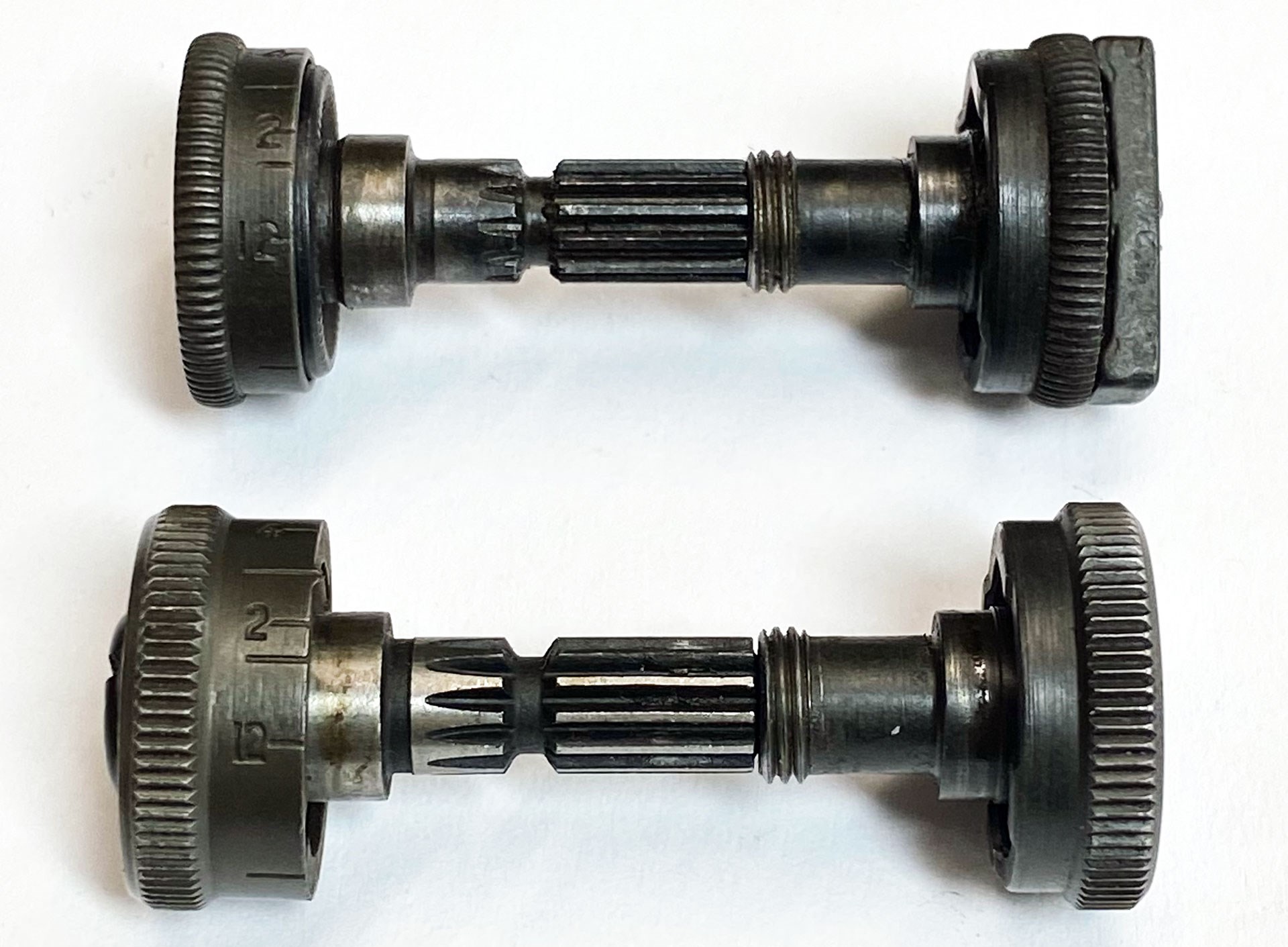 A World War II-era type three locking bar assembly on top compared with a post-war T105E1 assembly.
Both knobs have the same adjustment function as the earlier versions and it also assembles in the same manner, with a nut on the windage knob threading onto the end of the pinion to secure the assembly. However, that is largely where the similarities end. In order to address the issues that cause problems with the flush nut, yet retain the ability to freely adjust the knobs without having to use a lock bar, the T105E1 assembly moved the location of the compressing spring from the windage knob to the elevation knob. The flat spring is housed within the knob, and can be tensioned with the use of a large screw on the outside face of the knob.
The knobs are noticeably longer than the earlier versions, and also have larger serrated edges for better purchase when making adjustments. Instead of the pinion interfacing with the receiver cuts, the elevation knob itself has a single indent. With the nut of the windage knob securing the elevation knob and pinion assemblies, the elevation knob can be adjusted in a similar way as the earlier knobs to a desired range once the zero has been set. This is accomplished by loosening the large screw on the outer face of the knob and then retightening once it is set.
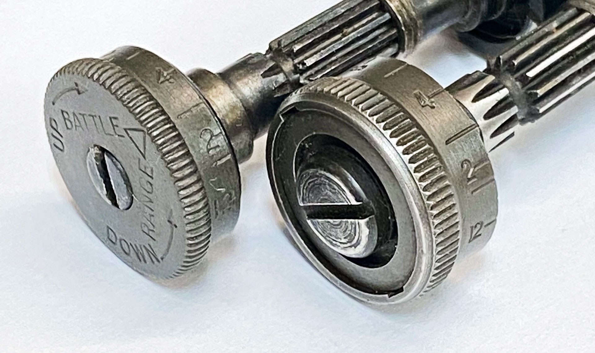 The earlier elevation knob design on the left, compared with the T105E1 on the right.
With its ability to adjust freely without the risk of coming loose or needing to lock up, the T105E1 is the perfected M1 rear sight knob and pinion assembly, and was the last variation to be used on the M1. Yet, despite its development and adoption during World War II, it was never implemented into wartime production. In fact, ordnance orders to swap over to the new assembly were not passed down until sometime after the war ended.
The decision to not immediately swap from the locking bars to the T105E1 during the war was likely made with production in mind, as swapping over to the new assembly would have required new jigs and tooling. Regardless, the T105E1 is superior in design to the earlier versions, and it was used on all post-war production rifles. While many World War II production M1s retained their earlier sight assemblies after the war and into the 1950s, many were eventually swapped out during the post-war period by arsenals for the newer assembly. Because of this, it is the most common type seen on M1 rifles today.
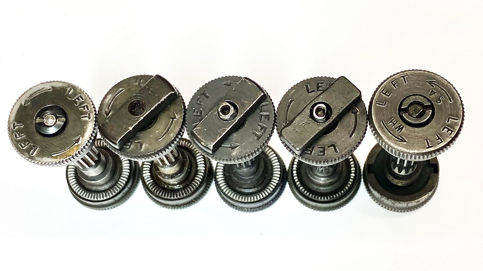 Another comparison of the the various versions of the M1 rear sight knobs and pinions used throughout Springfield Armory production, from left to right, with the flush nut with short pinion, type one locking bar with short pinion, type two locking bar with long pinion, type three locking bar with long pinion and a T105E1 assembly.
It was also carried over onto the design of the M-14 rifle with the rest of the rear sight assembly, and is still used on current production Springfield Armory, Inc. M1A rifles. The fact that this rear sight design has carried on for as long as it has is only one of the many hints to the brilliance of its inventor, despite the problems that had to be overcome along the way. This evolutionary history is just one of the many aspects that gradually change on the M1 through its career, and offers some insight into the ingenuity of John C. Garand.
Most Popular